This article is the 15th in our series of white papers on radiologic patient positioning techniques for x-ray examinations. If you'd like to comment on or contribute to this series, please e-mail [email protected].
The standard radiographic examination for evaluating the lumbar spine includes the anteroposterior, lateral, and oblique projections, supplemented by coned-down lateral films of the lumbosacral junction (L5-S1). The anteroposterior (AP) view is usually sufficient for evaluating traumatic conditions involving vertebral bodies and transverse processes, and the intervertebral disk spaces are also well demonstrated, except for the lowest (L5-S1). The spinous processes and articular facets however are not well demonstrated on this projection.
On the lateral projection of the lumbar spine, the vertebral bodies are seen in profile and the superior and inferior end plates are well demonstrated. Fractures of spinous processes are adequately evaluated on this projection, as are abnormalities involving the intervertebral disc spaces, including L5-S1.
Oblique views are particularly effective in demonstrating the facet joints (articular facets). Examination of motion in the lumbar spine may provide useful information. To accomplish this, lateral radiographs may be obtained during flexion and extension, and frontal radiographs may be obtained during lateral bending of the spine.
AP (or PA) projection of the lumbar-lumbosacral spine
The frontal radiograph of the lumbar spine can be obtained in the posteroanterior (PA) or AP projection with the patient erect or recumbent. Although the AP projection is more commonly used, there are some advantages to the PA projection.
Because the patient is in a prone position in the PA projection, the natural lumbar curvature is placed in such a way that the intervertebral disk spaces are parallel to the diverging beam of radiation, thus allowing better visualization of the intervertebral disc spaces. Moreover, the PA projection is more comfortable for patients who have back pain.
An additional advantage is lower radiation dose for females (25%-30% less for a PA projection compared with AP projection). A disadvantage of the PA projection for a patient with a large abdomen is the increased object to image distance (OID) of the lumbar vertebra, which results in radiographic distortion.
Technical factors
- Image receptor (IR): 14 x 17 inch (35 x 43 cm) for the lumbosacral spine, 11 x 14 inch (30 x 35 cm) for the lumbar spine only
- 75- 80 kVp range, some department protocols require use of a higher kVp (85-92) with reduction of mAs
- mAs 15 (at 80 kVp)
- Moving or stationary grid
- Surface to image distance (SID) of 48 inches (122 cm) is recommended to reduce distortion
Positioning for the AP projection of the lumbar-lumbosacral spine
- The patient is positioned supine on the radiographic table, with the hips and knees flexed and the head on a pillow so that their back is in firm contact with the table. Flexion of the knees and hips straightens the spine, reduces the lumbar curvature (lordosis), and brings their back closer to the table and their vertebral column more parallel to the IR. This better delineates the vertebral bodies and opens intervertebral disk spaces.
- If the patient is having excruciating back pain and is unable to assume a recumbent position, an AP or PA projection can be performed in an upright position. The upright position is also useful for demonstrating the natural weight-bearing status of the spine.
- Place the patient’s hands on the upper chest. Center the midsagittal plane of the patient’s body to the midline of the grid/table, with the shoulders and hips lying in the same horizontal plane.
- Central Ray (CR): Carefully palpate the superior portion of iliac crest (this corresponds to the L4-L5 intervertebral disc space) and direct the CR at this level, perpendicular to the cassette. Centering the CR to the iliac crest level will demonstrate both the lumbar spine and sacrum if a 14 x 17 inch (35 x 43 cm) cassette is used. If only a lumbar examination is intended, use an 11 x 14 inch (30 x 35 cm) cassette and direct the CR 1-½ inches (3.8 cm) above the iliac crests (L3).
- Place a contact shield over the gonads without obscuring the area of interest.
- Ask the patient to suspend their breathing on expiration.
- Some radiologists prefer that the AP projection be performed with the collimator open to the cassette size, especially in trauma patients. This provides additional information about the abdomen, such as air or bowel gas patterns.
Evaluation criteria
- Lumbar vertebral bodies, disk spaces, spinous and transverse processes, lateral margin of psoas muscle, SI joints, and the sacrum should be clearly demonstrated. For a lumbosacral spine examination, T11 to the distal sacrum should be included; for a lumbar examination, T12 to S1 should be included.
- There should be no rotation of the vertebral column. Rotation can be evidenced on a radiograph by looking at following areas:
- Spinous processes in the midline of the vertebral bodies.
- Right and left transverse processes equal in length.
- Symmetric vertebrae.
- Sacroiliac joints demonstrate equal distance from the spine.
- Optimal exposure should clearly demonstrate soft tissues as well as margins of psoas muscle and bony vertebrae.
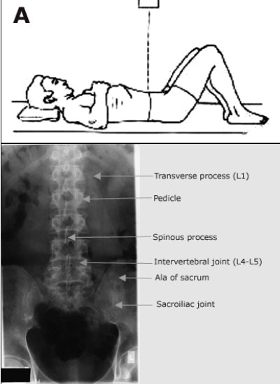 |
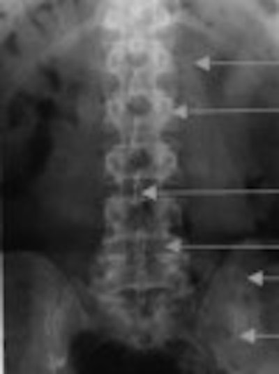
| For an AP projection of the lumbar spine, the patient is supine on the table, with their hips and knees flexed to eliminate the normal physiologic lumbar lordosis. The CR is directed vertically to the center of the abdomen at the level of the iliac crests. The radiograph in this projection demonstrates the vertebral bodies and the intervertebral disk spaces. The spinous processes are seen enface, appearing as teardrops, and the pedicles, also visualized enface, project as oval densities on either side of the bodies. Image courtesy of Dr. Naveed Ahmad. |
Lateral projection of the lumbar-lumbosacral spine
Technical factors
- IR: 14 x 17 inch (35 x 43 cm) for the lumbosacral spine, 11 x 14 inch (30 x 35 cm) for the lumbar spine only
- 85-90 kVp range for the lumbosacral spine (the lateral position requires a higher kVp than a spine position because of increased part thickness)
- mAs 50
- Moving or stationary grid
- Minimum SID of 40 inches (100 cm)
Positioning for lateral projection of the lumbar-lumbosacral spine
- The patient is positioned either recumbent or upright on the radiographic table with a pillow for the head (use the same body position as for PA or AP projection).
- Ask the patient to turn onto the affected side so that the mid-coronal plane of the body is aligned to the midline of the grid, then place a radiolucent support under the waist and adjust it so that the long axis of the spine is horizontal (parallel to the table).
- To better maintain a true lateral position, flex the patient’s hips and knees to a comfortable position. Their knees should be exactly superimposed to prevent rotation. Place a support (a small sandbag) between their knees to ensure no movement.
- If the patient has a lateral curvature (scoliosis) of the spine, they should be placed in whichever lateral position places the convexity of the spine down. This helps open the intervertebral spaces.
- If the lateral projection is performed in the upright position, ensure that the patient stands straight with weight equally distributed on the feet and hands above the head (having the patient grasp an IV stand with both hands at shoulder height helps to achieve immobilization).
- Place a contact shield over the gonads without obscuring the area of interest.
- Ask the patient to suspend their breathing on expiration.
- CR: Direct the CR perpendicular to the long axis of the spine. When using a 14 x 17 inch (35 x 43 cm) cassette for a lumbosacral spine examination, center it at the level of the iliac crest (L4-L5). When using an 11 x 14 inch (30 x 35 cm) cassette for a lumbar spine examination, center it 1-1/2 inches (3.8 cm) above the iliac crest. Sometimes the long axis of the spine cannot be adjusted horizontal (parallel to the table), due to the patient’s body habitus (this is especially true for women with a wide pelvis). In those cases a 5°-10° caudad angulation of the CR is desired.
- Close collimation is necessary for lateral spine radiographs. The vertebral column should be centered to the collimated field.
- A coned-down lateral projection of the lumbosacral junction also is included as part of a routine lumbosacral spine radiographic examination to better delineate spondylothisthesis (forward movement of one vertebrae in relation to another) involving L5-S1. An 8 x 10 inch (18 x 24 cm) cassette is used. Use the same body position as for a lateral lumbar spine study with a radiolucent support under the lower thorax so the long axis of the spine is horizontal. The CR is centered on a coronal plane 2 inches (5 cm) posterior to the anterior superior iliac spine (ASIS) and 1 ½ inches (3.8 cm) inferior to the iliac crest. The ASIS is easily palpated in all patients when they are lying on their side.
Evaluation criteria
- Lumbar vertebral bodies, intervertebral foramina, disk spaces, spinous and transverse processes, SI joints, and sacrum should be clearly demonstrated. For a lumbosacral spine examination T11 to the distal sacrum should be included; for a lumbar examination T12 to S1 should be included.
- There should be no rotation of the vertebral column. Rotation can be evidenced on a radiograph by looking at following areas:
- Nearly superimposed iliac crests when the x-ray beam is not angled.
- Superimposed posterior margins of each vertebral body.
- Open intervertebral disc spaces.
- The vertebrae should be aligned down in the middle of the radiograph.
- The L5-S1 lumbosacral junction lateral projection should demonstrate the lower one or two lumbar vertebrae and the upper sacrum with lumbosacral joint in the center of the radiograph.
- Optimal exposure should demonstrate clearly soft tissues as well as joint spaces and bony vertebrae.
Oblique projection of the lumbar-lumbosacral spine
As in the cervical spine, an oblique projection of the lumbar spine can be obtained from either the patient’s anterior or posterior aspect, although the PA oblique projection is preferable. Oblique radiographs allow evaluation of the posterior elements of the lumbar spine (lamina, pedicle, the facet joints, and intervertebral foramina) although some regard the oblique projections as unnecessary.
The L5 intervertebral foramina (right and left) are not usually well visualized on the lateral projection because of their oblique direction. Consequently, oblique projections are used for these foramina. When oblique projections are indicated, they are generally performed after the AP projection and in the same body position (recumbent or upright). For comparison, radiographs are generally obtained from both sides (right and left oblique).
Technical factors
- IR: 14 x 17 inch (35 x 43 cm) or 11 x 14 inch (30 x 35 cm), lengthwise
- 75- 80 kVp range, some department protocols require use of a higher kVp (85-90) with reduction of mAs
- mAs 15 (at 85 kVp)
- Moving or stationary grid
- Minimum SID of 40 inches (100 cm)
Positioning for oblique projections of the lumbar-lumbosacral spine
- Have the patient in a semi-supine (right posterior oblique and left posterior oblique) or semi-prone (right anterior oblique and left anterior oblique) position by elevating their shoulder, hip, and knee so that the patient turns from the supine position toward their side, approximately 30°-45°. A support may be placed under the elevated shoulder, hip, and knee. This helps to bring the facet joints closest to the cassette.
- A 45°oblique from the plane of the table visualizes the facet (zygopophyseal joints) at L1-L4, whereas a 30° oblique from the plane of the table visualizes L5-S1 to a better advantage.
- The long axis of the spine should be horizontal (parallel to the table) and in the midline of the grid.
- CR: Direct the CR perpendicular to the midpoint of the cassette, entering 2 inches (5 cm) medial to the ASIS and 1 ½ inches (3.8 cm) above the iliac crest.
Evaluation criteria
- The oblique projections of the lumbosacral spine should demonstrate the articular process and facet joints of the side closest to the cassette. They should be open and uniformly visible through the vertebral bodies.
- Adequate rotation of the spine is evidenced by the position of the pedicles. If the pedicle is anterior on the vertebral body, the patient is not rotated enough, if the pedicle is posterior on the vertebral body, the patient is rotated too much.
- Both sides should be examined for comparison.
- When the patient has been properly positioned in a 30°-45° oblique position, the articular process and facet joints have the appearance of "Scottie dogs."
AuntMinnie.com contributing writer
June 19, 2003
Related Reading
Radiographic positioning techniques for the cervical spine, March 26, 2003
Boning up on humerus, clavicle, and AC joint positioning, February 18, 2003
Getting the most from shoulder positioning, December 24, 2002
The bends and flexures of forearm and elbow x-ray positioning, November 21, 2002
The twists and turns of hand and wrist x-ray positioning, October 15, 2002
Copyright © 2003 AuntMinnie.com


