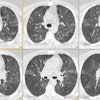
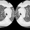
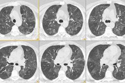
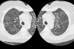
Pulmonary Anatomy:
The lungs have a dual vascular supply- both pulmonary and systemic. The normal pulmonary circulation is a low pressure system that has approximately one-sixth the flow resistance of the systemic pulmonary circulation [18]. The pulmonary arteries account for 99% of the arterial blood supply to the lungs and take part in gas exchange [9]. The pulmonary arteries begin at the pulmonic valve and divide within the pericardium into right and left branches (i.e.: the main, left, and right pulmonary arteries are intrapericardial [18]). The right artery divides into an anterior trunk (to the right upper lobe) and a large inferior trunk that supplies both the middle and lower lobes. The portion of the inferior right trunk that lies between the lower and middle lobes in the major fissure is called the interlobar artery. Pulmonary arteries travel within the center of lobules along with the bronchial tree. Pulmonary veins travel separate from the arteries and can be distinguished by the fact that they are unaccompanied by bronchi, and that they extend toward the left atrium. Therefore, lower lobe veins travel in a more horizontal direction, and upper lobe veins in a more vertical direction than the arteries.
A systemic bronchial circulation
arises from the thoracic aorta to supply the airways, pulmonary
arteries, and veins (vasa vasorum) to the level of the terminal
bronchioles. They also supply the visceral pleura and the vasa
vasorum of the thoracic aorta [32]. The bronchial circulation
draws about 1% of the systemic circulation [18]. The bronchial
arteries most commonly (over 70% of individuals [9]) originate
from the descending thoracic aorta between the T3 and T7 vertebrae
(usually between the superior end plate of T5 and the inferior end
plate of T6 [9]). Bronchial arteries that arise from this expected
location (between T5 and T6) are called orthotopic bronchial
arteries [9,12,32]. Arteries that arise from elsewhere along the
aorta are considered ectopic [12,32]. There is generally a large
amount of anatomic variability with respect to the origins and
branching patterns of the bronchial circulation [12]. About 60% of
individuals have a single right bronchial artery that most
commonly arises as a intercosto-bronchial artery trunk from the
posterolateral aspect of the thoracic aorta. The left bronchial
arteries usually originate from the anterior surface of the
thoracic aorta or from the concavity of the aortic arch, pass
forward beside the lateral wall of the esophagus, and cross the
peribronchial space from the level of the left main bronchus
toward the hilum [12]. Multiple bronchial arteries are more common
on the left (70% of individuals) and they are less likely to
originate with an intercostal artery [4]. The most common
bronchial artery pattern is one right intercostobronchial trunk
and two left bronchial arteries (found in about 40% of patients)
[12]. Up to 35% of individuals have aberrant bronchial arteries
which arise from intercostal arteries, internal mammary arteries,
the thyrocervical or costocervical trunk, or from the inferior
aspect of the aortic arch [4]. The normal bronchial artery is less
than 2 mm in size at their origin and 0.5 mm distally as they
enter the bronchopulmonary segment [6,32]. The bronchial
circulation often dilates in patients with inflammatory conditions
that affect the lungs and airways [32]. Abnormally dilated
bronchial arteries measure greater than 2mm and often have a
tortuous mediastinal course [32].
The bronchial vasculature feeding the intrapulmonary airways is situated close to the pulmonary arteries at the level of the vasa vasorum and the two systems are connected by anastomoses between the systemic and pulmonary capillaries [9]. Therefore, the venous drainage of the bronchial circulation is by way of both systemic and pulmonary veins. Drainage by means of the pulmonary veins produces a small left to right shunt in all individuals.
Trachea: The upper limited of normal for the coronal and sagittal measurements of the trachea are 25mm and 27mm, respectively in men; and 21mm and 23 mm, respectively in women [5]. The trachea changes from a round or oval configuration during inspiration to a horseshoe shape at end expiration with variable degrees of invagination of the posterior membranous portion. The cross-sectional area is reduced by approximately 35% in expiration.
Junction lines: The anterior junction line is seen on 25-57% of frontal CXR's [20]. It is formed by the apposition of the anterior portions of the left and right lungs (4 abutting layers of viseral and parietal pleura) and a small amount of intervening mediastinal fat [20]. It typically has a slightly oblique course from the upper right to the lower left and it overlies the superior 2/3's of the sternum [20]. The anterior junction line does not extend above the manubrial sternal junction. The posterior junction line is formed by the apposition of the posterior portions of the left and right lungs and it is seen on about 32% of PA CXR's [20]. It projects as a straight or mildly leftward convex line through the trachea in the upper part of the chest above the level of the aortic arch (it extends above the clavicles- unlike the anterior junction line- and is usually seen at the level of T3 to T5) [20,21].
Right paratracheal stripe: On the PA chest radiograph the right paratracheal stripe appears as a thin soft tissue band along the right tracheal border. It is composed of the tracheal wall, mediastinal connective tissue, and the parietal and visceral pleura. It can be seen on up to 97% of PA CXR's [20]. A normal right paratracheal stripe should be uniform in width and measure between 1 to 4 mm [20]. A thickness of greater than 5 mm may be an indicator of pathology in this location (adenopathy). A increase in width over time, however, is more worrisome than a single measurement as fat or vascular structures may occasionally produce widening of the stripe.
Left paratracheal stripe: A left paratracheal stripe can be found on 21-31% of PA CXR's.
Aortic-pulmonary stripe: This represents a mediastinal reflection or interface formed by the pleura of the anterior left lung coming in contact with and tangentially reflecting over the left pulmonary artery and aortic arch [20]. The stripe is usually straight or mildly convex, crossing laterally over the aortic arch and main pulmonary artery [20].
Aorto-pulmonary window: This is a mediastinal space that lies posterior to the aorto-pulmonary stripe [20]. It is bounded superiorly by the inferior wall of the aortic arch and inferiorly by the superior wall of the left pulmonary artery [20]. The posterior wall of the ascending aorta forms the anterior boundary and the posterior boundary is formed by the anterior wall of the descending aorta [20]. The left lung extends into this space the contour should always be concave or straight [20]. A convex contour of the AP window is considered abnormal [20].
Posterior tracheal stripe: This stripe is composed of the posterior tracheal wall, mediastinal tissue, and parietal and visceral pleura. A posterior tracheal thickness of greater than 2.5 mm is abnormal, or indicative of a tracheoesophageal stripe. A clue to the presence of a tracheoesophageal stripe (in which the anterior wall of the esophagus contributes to the thickness of this stripe) is that it will extend below the level of the azygous/ aortic arch. The azygous arch ordinarily blocks the right lung from extending posterior to the trachea below this level. A tracheoesophageal stripe greater than 5 mm should be considered abnormal, however, a collapsed esophagus can also produce a thick shadow in this location.
Retrotracheal triangle: This clear space is bordered anteriorly by the posterior wall of the trachea. The anterior aspects of the upper thoracic vertebral bodies form the posterior border. Superiorly the space is bordered by the thoracic inlet, and inferiorly by the aortic arch. Increased opacity in this region may indicate the presence of pathology. On occasion, a tortuous or aberrant subclavian vessel may produce a density in this area.
Azygo-esophageal recess: The line is produced by differences in density between the mediastinum and the posteromedial portion of the right lower lobe [20]. The recess produces a smooth interface over the lower thoracic spine running from the subcarinal region to the diaphragmatic hiatus [20].
Right paraspinal line: This line is formed by the contact between the right lung with the posterior mediastinal soft tissues [20]. It actually represents a mach effect and should be smooth and straight and abut the vertebral bodies (extending from the 8th through 12 thoracic vertebral levels) [20]. The line can be displaced laterally by osteophytes or posterior mediastinal fat, but a mass lesion should be excluded [20].
Left paraspinal line: This line is formed by tangential contact of the left lung and pleura with the posterior mediastinal fat, left paraspinal muscles, and adjacent soft tissues [20]. It lies medial to the lateral shadow of the descending aorta and extends from the aortic arch to the diaphragm [20]. It is seen more frequently (about 41% of PA CXR's) than a right paraspinal line [20].
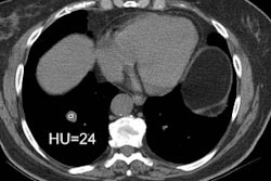
Bleb: A bleb is a small gas-containing space within the visceral pleura or the subpleural lung that is not larger than 1 cm [24]. It appears as a thin-walled cystic airspace contiguous with the pleura [24].
Bulla: An airspace measuring more than 1 cm in diameter (they can be quite large) sharply demarcated by a thin wall that is no greater than 1 mm in thickness [24]. A bulla is usually accompanied by enphysematous changes in the adjacent lung [24]. On CT it appears as a rounded focal lucency 1 cm or more in diameter bounded by a thin wall [24].
Cyst: A cyst is any round circumscribed space that is surrounded by an epithelial or fibrous wall of variable thickness (usually thin walled < 2mm) [24]. Cysts are seen without associated emphysema [24]. The cysts usually contain air, but occasionally contain fluid or solid material [24].
Pulmonary Ligaments: The pulmonary ligaments are composed of a double layer of pleura and extend inferiorly from the hila in a sheet-like manner, coursing laterally and posteriorly. The ligaments overlie a cleavage plane in the lower lobes referred to as the intersegmental septum. This separates the medial basal (or anteromedial basal) segment from the posterior basal segment. The lower margins can be continuous with the diaphragmatic pleura or can end in a free edge. (ACR syllabus #40; p.18)
Vagus Nerve: The right vagus nerve enters into the superior mediastinum by passing in front of the subclavian artery and posterior to the right inominate vein. More inferiorly it is located posteromedially to the right inominate vein and the superior vena cava. The left vagus nerve enters the mediastinum between the left subclavian artery and the left common carotid artery, before coursing caudally posterior to the left inominate vein. The recurrent laryngeal nerves arise from the vagus nerve. On the right side, the recurrent laryngeal nerve loops under the right subclavian artery and runs superiorly in the tracheo-esophageal groove. The left recurrent laryngeal nerve loops under the ligamentum arteriosum in the chest before running superiorly in the tracheo-esophageal groove.
Phrenic Nerve: The phrenic nerve descends anterior to the anterior scalene muscle and subclavian artery, but posterior to the subclavian vein. It enters the mediastinum at the level of the internal mammary artery orifice. The right phrenic nerve descends lateral to the right inominate vein and SVC, while the left nerve descends anterior to the left subclavian artery. In the chest, the nerve courses along the medial aspect of the mediastinum to reach the diaphragm. The left phrenic nerve passes of the left ventricular pericardium [23]. The nerve passes at a distance of less than 3 mm from the left marginal vein [23]. Following biventricular pacing, left phrenic nerve stimulation is a recognized complication [23]. The phrenic nerve can also be injured during cardiac surgery in 2-31% of patients [25]. In 60-90% of patients with phrenic nerve injury after cardiac surgery, the radiographic abnormality has been noted to resolve within one year [25].
Inferior cervical ganglion (Stellate ganglion): The inferior cervical ganglion lies between the base of the transverse process of C7 and the neck of the first rib. It is superior and posterior to the subclavian artery and is located immediately posterior to the vertebral artery.
Brachial plexus: The brachial plexus arises from the C5 to T1 nerve roots and runs between the anterior and middle scalene muscles.
Thoracic duct: The thoracic duct is located in the posterior mediastinum and is the common truck of the lymphatic system that drains into the vascular system [19]. It begins at the level of the cisterna chili- a lymphatic confluence typically located within the posterior mediastinum at the level of L1 [19]. The cisterna chyli is usually located to the right of the aorta and it can be seen in about 2% of patients at CT (low attenuation near water density) and 15-96% of patients at MR [26]. The duct then ascends superiorly through the right posterior chest [19]. At the level of T4 the duct crosses to the left and continues superiorly forming an arch that rises 4-5cm above the clavicle [19]. The duct then travels forward running posterior to the left common carotid artery and ends in the posterolateral aspect of the confluence of left internal jugular vein and subclavian vein [19]. The duct can also end at other sites including the left internal jugular vein, brachiocephalic vein, or left subclavian vein [19].
Parenchymal Anatomy:
The trachea consists of inner mucosal and submucosal layers, cartilage and muscle, and an advential layer [31]. There are 16 to 22 c-shaped anterior cartlagenous rings [31]. Because the cartilagenous rings are incomplete, the posterior wall is formed by the thin trachealis muscle [31]. The bronchi are differentiated from bronchioles by the presence of cartilage in their walls [31]. The normal coronal tracheal dimension ranges from 13-25 mm in men and from 10-21 mm in women [31]. The sagittal diameter ranges from 13-27 mm in men and 10-23 mm in women [31]. At end-expiration the cross-sectional area decreases secondary to anterior movement of the noncartilagenous posterior wall [31]. The blood supply to the trachea is dervied from the inferior thyroid, bronchial, and intercostal arteries [31]. The peribronchovascular interstitium is a system of fibers that surrounds the bronchi and pulmonary arteries- forming a strong connective tissue sheath that encases these structures in the perihilar region [13]. This interstitium continues to the lung periphery where is also invests the small centrilobular bronchioles and arteries [13].
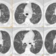
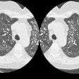
The secondary pulmonary lobule refers to the smallest unit of lung structure marginated by connective tissue septae [13]. Secondary lobules typically measure between 1 to 2.5 cm in diameter and the septae extend from the pleural surface inward [13]. The pulmonary veins and lymphatics lie within the interlobular septae [13] (small, non-encapsulated lymph nodes within the septa can enlarge and may be considered in the differential of a small, sub-pleural solitary pulmonary nodule). Secondary lobules are more difficult to identify centrally because they are more irregular in shape and the septae are thinner and less well define than peripherally [13]. Interlobular septae are usually visible as very thin, straight lines of uniform thickness that are usually 1 to 2.5 cm in length and perpendicular to the pleural surface. In healthy patients, only a few septa are visible in the lung periphery and are best appreciated in areas in which they are best developed such as the anterior apices and along the mediastinal pleural surface [13]. Each secondary pulmonary lobule is supplied by a centrilobular bronchovascular bundle which consists of a small central bronchiole (about 1 mm in diameter, however, it's wall thickness is only about 0.15 mm which is below the resolution of HRCT) and a pulmonary artery (about 0.7-1.0 mm in diameter) which frequently appears as a linear or dot like opacity within the center of a lobule about 1 cm from the pleural surface [13]. Centrilobular nodules can reflect the presence of either interstitial or airspace disease [13].
The terminal bronchiole is the last conducting airway and it contains smooth muscle, but no cartilage in it's wall. The number of branches required to go from a main bronchus to a terminal bronchiole is quite variable, but an average number of divisions is 14. Each terminal bronchiole supplies a primary lobule or acinus (the acinus contains respiratory bronchioles, alveolar ducts, and alveoli [24]). The acinus is the structural portion of lung parenchyma, subserved by a single terminal bronchiole, that participates in gas exchange [13,24]. Each terminal bronchiole gives rise to 5 to 10 respiratory bronchioles in which both conduction and gas exchange (due to alveoli in their walls) take place. The respiratory bronchioles in turn give rise to numerous alveolar ducts. The alveolar ducts are devoted solely to gas exchange- their walls contain no mucosa, only alveoli (approximately 20 alveoli per alveolar duct). The final generation of airway prior to the alveoli themselves are the alveolar sacs which are also composed of alveoli. There are approximately 300 million alveoli in the lung.
Each secondary lobule is composed of a variable number of pulmonary acini- ranging from 3 to 24 [13]. The acinus ranges in size from 6 to 10 mm in diameter [24]. The acinus is crossed centrally by a bronchovascular bundle consisting of a respiratory bronchiole and a corresponding acinar artery (0.2 to 0.5 mm). This small acinar artery may be seen in normal subjects to within 3 to 5 mm of the pleural surface. An intralobular interstitium consisting of a very fine web of connective tissue supports the intralobular structures [14]. The intralobular interstitium is not normally visible on HRCT exams [8]. The resistance to airflow in airways less than 2 mm in diameter accounts for only 25% of the total airway resistance. Because of the small contribution to total resistance by the small airways, pathology affecting these airways must be extensive to have an appreciable change in total resistance. In fact, patients with emphysema can destroy as much as 30% of their lungs before pulmonary function tests become abnormal [15,16]
Collateral connections can result in continued aeration of lung
distal to sites of bronchial obstruction. Adjacent alveoli are
connected by the pores of Kohn, while the canals of Lambert
provide connections between small bronchioles and adjacent
alveoli. These collateral pores are less well developed in
children, who are thus more prone to develop atelectasis in the
presence of bronchial disease than adults.
The Heart and Great Vessels:
In an adult, the greatest transverse diameter of the heart should be less than 50% of the largest transthoracic dimension on an erect, well inflated PA chest radiograph. The diameter of the cardiac silhouette may vary between 0.3 and 1.7 cm from ventricular diastole to systole. Changes are more pronounced in individuals with heart rates below 60 beats per minute [10]. In pediatric patients the heart tends to be more globular in shape- the usual adult appearance is generally seen between age 6 to 8 years. The left atrial appendage is the only portion of the left atrium that forms part of the left border of the heart. On PA radiographs it occupies the portion of the left heart border between the main pulmonary artery segment and the superior portion of the left ventricular contour. When left atrial pressure and volume are normal, this segment of the left heart border is concave. Early or mild enlargement of the left atrium may be detected as enlargement of the left atrial appendage with straightening of this segment of the left heart border. With continued enlargement, this segment will become convex. On cardiac echo, the RV ranges from 2.2 to 4.4 cm in maximum diameter on the apical 4-chamber view [22]. On a PA CXR, the right ventricle is not normally a border forming structure [22]. Signs of RV dilatation on the PA CXR include dilatation of the pulmonary trunk, increased convexity of the left upper cardiac contour, and an upturned cardiac apex [22]. On the lateral view, the RV enlarges superiorly and anteriorly behind the sternum [22]. The right atrium forms the right heart border on the PA CXR and is considered enlarged when the right heart border extends 5 cm or greater from the midline [22]. On cardiac echo, the RA measures 3 to 4 cm in diameter on the apical 4-chamber view [22].
The main pulmonary artery segment of the left heart border is composed of the main pulmonary artery and proximal portion of the left pulmonary artery. Through adolesccence the apparent size of the main pulmonary artery remains increased. As the main pulmonary artery passes over the left atrial appendage, the right pulmonary artery arises and crosses over the top of the left atrium. The left pulmonary artery represents the continuation of the main pulmonary artery. On the lateral radiograph, the right pulmonary artery appears as an oval or rounded density anterior to the tracheal air column at the level of the carina. The left pulmonary artery forms a shepard's crook configuration as it passes over the left bronchus, behind and slightly superior to the right pulmonary artery.
In a young patient, the normal contour of the ascending aorta should not extend to the right of the vascular pedicle of the right hilum or shadow of the superior vena cava. Enlargement of the ascending aorta can occur as a result of aortic vavular stenosis (with post-stenotic dilatation), or as a result of an ascending aortic aneurysm (due to intrinsic disease such as Marfans). The aotra can become tortuous in patients with underlying hypertension and in the elderly. The superior vena cava forms the upper half of the right heart border on the frontal radiograph. The caval shadow is fairly straight and lies parallel to and to the right of the tracheal air column. The cavo-atrial junction lies at the level of the third costal cartilage (anteriorly) and the seventh thoracic vertebra (posteriorly).
The anteromedial portion of the interatrial septum is separated from the posterolateral portion by the fossa ovalis [11]. The crista terminalis is the muscular prominence on the posterolateral surface of the right atrium extending from the orifice of the superior vena cava to that of the inferior vena cava [11].
The azygous vein originates at the junction of the right ascending lumbar and subcostal veins, enters the chest through the aortic hiatus, and ascends along the anterolateral aspect of the thoracic spine [1]. At T5-T6 it arches anteriorly just above the level of the right main bronchus and drains into the SVC (it should measure 10 mm or less at this level) [1]. An anomalous course of the azygous vein in the right lung apex produces an "azygous lobe" in 0.4 to 1.2% of the population [1,27]. An azygous lobe occurs when the azygous vein penetrates the lung, carrying along pleural layers that entrap a portion of the right upper lobe [27]. The ayzgous vein is visible in the lowermost part of the fissure as a tear-shaped shadow [27]. Because the two layers of pleural forming the fissure are not fused, pleural fluid and air can track into this space [27].
The hemiazygous vein originates at the junction of the left ascending lumbar and left subcostal veins [1]. It often receives tributaries from the left renal vein and IVC [1]. The hemiazygous ascends along the left anterolateral aspect of the thoracic spine and at the level of T8-T9 it crosses to the right anterior to the aorta to join the azygous vein [1]. From this point, the accessory hemiazygous vein extends further cephalad in a left paravertebral location [1]. The left superior intercostal vein drains the left 2nd through 4th intercostal spaces and communicates with the accessory hemiazygous vein in 75% of patients [1]. It then arches ventrally adjacent to the aortic arch and drains into the left brachiocephalic vein [1]. When seen en face on CXR this produces the aortic nipple [1].
Monitoring and Therapeutic Devices:
Endotracheal tubes: The ideal position for the ETT is in
the mid-trachea approximately 5 cm from the carina with the head
in neutral positioning [28]. The tip of the ETT moves with the
chin- therefore with flexion it moves inferiorly (up to 2cm-
therefore the tip should be more than 2 cm from the carina with
the head in a neutral position), and with extension it moves
superiorly [28]. If the ETT is too high, there is a risk of either
inadvertent extubation or hypopharyngeal intubation which can
cause ineffectiv ventilation and gastric distention [28]. In
addition, the ETT's occluding cuff may cause vocal cord injury
(the tip of the ETT should be at least 3 cm below the vocal cords)
[28]. The cuff should normally not measure more than 2.5 cm in
diameter, and it should certainly not produce a bulge in the
tracheal walls or project below the tip of the ET
tube.Overinflation of the balloon to 1.5 times the diameter of the
normal trachea has been shown to cause tracheal injury [28]. An
ETT-related tracheal rupture usually invovles the membranous
posterior wall typically within 7 cm of the carina [28].
Radiologic indications of tracheal rupture include subcutaneous
emphysema, pneumomediastinum or pneumothorax, right oblique
displacement of the distal portion of the ETT, overdistention of
the ETT balloon (over 2.8 cm), and reduced balloon-to-tip distance
(less than 1.3 cm; normal distance is 2.5 cm) [28].
Tracheostomy Tubes: The tip of the TT should be located
one-half to two-thirds the distance between the tracheal stoma and
the carina- at about the level of the third thoracic vertebral
body [28]. The lumen of the tube should be about 2/3's the
tracheal diameter and the cuff should hug, but not distend the
tracheal wall. Neck flexion and extension do not affect the
position of the TT [28].
Chest tube: The tip of
the chest tube should ideally be aimed apically for a pneumothorax
evacuation and basally for fluid drainage [28]. The side hole of
the tube should always be positioned medial to the inner margin of
the ribs [28]. An intrafissual position of the tube should be
suspected on the frontal CXR when the tube has a horizontal or
slightly oblique upward course [28].
Central venous catheter:
The CVC tip should be located in the SVC, below the anterior first
rib and above the right atrium [29]. Placement in the RA can
result in arrhythmias or myocardial rupture [29].
Swan-Ganz Catheter: The tip of the catheter should be 2 to 3 inches distal to the bifurcation of the main pulmonary artery, but should not extend beyond the proximal interlobar pulmonary arteries (the tip should ne within 2 cxm of the hilum [29]). Complications of Swan-Ganz catheterization include pulmonary artery rupture (0.001- 0.5% of cases) which is associated with a mortality between 45-65%. Rupture of the pulmonary artery usually occurs when the catheter is advanced into the peripheral branches of the pulmonary artery to measure pressures. If the patient survives, a false aneurysm of the pulmonary artery (about 0.15% of cases) may result which can subsequently rupture itself. The rate of recurrent hemorrhage associated with a false aneurysm is between 30-40% and mortality is between 40-70%. Risk factors associated with pulmonary artery rupture include technical errors, anticoagulation, pulmonary arterial hypertension, long-term steroid therapy (fragile vessels), age greater than 60 years, and female sex. Technical errors can be avoided by inflating the balloon in a large pulmonary artery before pushing it distally and deflating the balloon before withdrawing it. Hemoptysis is the typical presenting symptom. Following rupture chest radiographs typically demonstrate an infiltrate which represents an area of hemorrhage. A false aneurysm may be detected as the infiltrate clears- leaving a rounded nodule or mass. Generally, the right pulmonary artery is involved (93% of cases)- and typically the lesion occurs in a lower or middle artery. CT with contrast will demonstrate the false aneurysm as an enhancing mass with an adjacent vessel and sometimes a partially thrombosed lumen. Percutaneous transcatheter embolization is the treatment of choice for a pulmonary artery false aneurysm. Differential considerations for a parenchymal infiltrate that appears after Swan-Ganz line placement includes an area of infarction. [17]
Intra-aortic Counterpulsation Device (Balloon Pump): The
intraaortic balloon pump (IABP) provides partial cardiovascular
assistance. This device enhances coronary artery blood flow,
decreases myocardial oxygen consumption, decreases left
ventricular afterload, and supplements cardiac output by 20-30%.
It is used for a short period of time to permit the myocardium
time to recover following bypass in certain patients. The device
consists of a catheter surrounded by an inflatable balloon
approximately 25 cm long, with a small cylindrical radioopaque
marker at the catheters distal tip [29]. The device is placed
percutaneously via a femoral artery. The balloon is sausage-shaped
and works by couterpulsation- inflating and deflating out of phase
with the cardiac cycle. By inflating during diastole, the pump
increases pressure and flow to the coronary and cerebral arteries
[33]. By deflating during systole, there is decreased cardiac
afterload, decreased left ventricular work, and decreased
myocardial oxygen consumption. The tip is optimally positioned
just distal to the take off of the left subclavian artery- about
2-4 cm below the level of the aortic arch (approximately 2 cm
above the carina [33])[3]. The balloon should not occlude the
carotid and subclavian arteries at their origin from the aortic
arch, or the renal or superior mesenteric arteries more distally.
If placed too distally, the pump also loses effectiveness. [2,3]
Complications of IABP placement are seen in 8-29% of procedures
[3]. Complciations include limb ischemia, vascular perforation,
aortic dissection (1-4% of IABO insertions [3,29]), mesenteric
ischemia, renal insufficiency, neurologic complications,
thrombocytopenia, and infection [3,33].
Ventricular assist devices:
LV assist devices are used as a bridge to heart transplantation or
to myocardial recovery [29].
The Impella assist device consists of a small pump located in the
proximal portion of the catheter (this would be located in the
ascending aorta) which can pump up to 2.5 L/min from the LV,
thereby reducing myocardial workload [29]. After the device is
properly positioned, blood is rapidly withdrawn by the microaxial
blood pump from the left ventricle and moved to the aorta thrugh
the outlet area (which is situated above the aortic valve in the
aorta) [33]. The catheter is placed so that the coiled pigtail end
is located in the central portion of the left ventricle [29,34].
The ideal location of the distal tip is 3-4 cm across the aortic
valve [33]. When the device is inserted too deep in the LV, pump
performance is suboptimal because of suctioning against the
lateral LV wall or apex (and this can lead to ventricular
arrhythmia or ventricular perforation) [33,34]. A position that is
too proximal (across the aortic valve or in the ascending aorta)
may result in diminished flow and potentially cause damage to the
aortic valve [34].
Click here to view a malpositioned intra-aortic balloon pump
Cardiac Pacemakers: An atrial electrode is usually placed
in the atrial appendage but is sometimes placed in the body of the
atrium or along the septum if the pacing threshold is favorable.
The ventricular lead is usually placed in the right ventricular
apex, an usual location may be chosen for electrode placement
depending on the pacing threshold or avoid pacing the diaphragm.
The electrode is usually secured by entrapping the tip in the
trabeculae of the right ventricle. Permanent fixation requires a
fibrous adhesion to form at the tip which takes weeks to occur.
Complications from pacer placement include electrode malposition (6%), taut or redundant lead (5%), electrode displacement, pneumothorax (3%), lead fracture, and myocardial perforation (0.5%). Leads can enter the left ventricle through a septal defect or can enter the cardiac veins. A lead entering the middle cardiac vein may appear to be appropriately located in the RV on the PA radiograph, but the course will be more posterior and inferior on the lateral image. Most cases (50%) of electrode dislodgement occur during the first two weeks, when a fibrous adhesion has not yet formed. Partial penetration of the myocardium is inferred if the electrode tip is within 3 mm of the epicardial fat and perforation is inferred if the tip extends into the epicardial fat. Adhesions between the lead and the tricuspid valve leaflets can produce tricuspid insufficiency and some authors recommend that no more than three leads be placed across the tricuspid valve. [7] Lead fracture or insulation damage most commonly occurs where the lead passes under the clavicle mmost likely due to repeated pinching [30]. Placement of ipsilateral subclavian catheters poses a risk to the pacemaker or ICD system, but the ipsilateral internal jugular vein can be used for catheter placement [30].
REFERENCES:
(1) AJR 2004; Demos TC, et al. Venous anomalies of the thorax. 182: 1139-1150
(2) Radiographics 1997; 17:1141-1155
(3) AJR 2005; Hurwitz LM, Goodman PC. Intraaortic balloon pump location and aortic dissection. 184: 1245-1246
(4) J Thorac Imaging 1998; Najarian KE, et al. Arterial embolization in the chest. 13: 93-104
(5) Radiol Clin North Am 1998; Stark P, et al. Imaging of the trachea and upper airways in patients with chronic obstructive airway disease. 36 (1): 91-105
(6) Radiology 1998; Song JW, et al. 208: 187-191
(7) AJR 1997; Imaging of cardiac pacemakers. 169: 1371-1379
(8) Radiol Clin N Am 2005; Gotway MB, et al. High-resolution CT of the lung: patterns of disease and differential diagnoses. 43: 513-542
(9) Radiographics 2006; Bruzzi JF, et al. Multidetector row CT of hemoptysis. 26: 3-22
(10) J Thorac Imag 1994; Boxt LM et al. Normal plain film examination of the heart and great arteries in the adult. 9: 208-218
(11) AJR 2006; Bruzzi JF, et al. When, why, and how to examine the heart during thoracic CT: Part I, basic principles. 186: 324-332
(12) AJR 2006; Chung MJ, et al. Bronchial and nonbronchial systemic arteries in patients with hemoptysis: depiction on MDCT angiography. 186: 649-655
(13) Radiology 2006; Webb WR. Thin-section CT of the secondary pulmonary lobule: anatomy and the image- the 2004 Fleischer lecture. 239: 322-338
(14) J Thorac Imag 1995, 10: p. 129-133
(15) J Thorac Imag 1995, 10: p.227-235
(16) J Thorac Imag 1995, 10: p.236-254
(18) Radiographics 2006; Castaner E, et al. Congenital and acquired pulmonary artery anomalies in the adult: radiologic overview. 26: 349-371
(19) AJR 2006; Liu ME, et al. Normal CT appearance of the distal thoracic duct. 187: 1615-1620
(20) Radiographics 2007; Gibbs JM, et al. Lines and stripes: where did they go?- from conventional radiography to CT. 27: 33-48
(21) Radiographics 2007; Whitten CR, et al. A diagnostic approach to mediastinal abnormalities. 27: 657-671
(22) AJR 2007; Cook AL, et al. Right heart dilatation in adults: congenital causes. 189: 592-601
(23) Radiographics 2007; Saremi F, Krishnan S. Cardiac conduction system: anatomic landmarks relavant to interventional electrophysiologic techniques demonstrated with 64-detector CT. 27: 1539-1567
(24) Radiology 2008; Hansell DM, et al. Fleishner society: glossary of terms for thoracic imaging. 246: 697-722
(25) AJR 2008; Thornton RH, et al. Phrenic nerve injury resulting from percutaneous ablation of lung malignancy. 191: 565-568
(26) Radiographics 2008; Restrepo CS, et al. The diaphragmatic crura and retrocrural space: normal imaging appearance, variants, and pathologic conditions. 28: 1289-1305
(27) AJR 2010; Villanueva A, et al. Migrating azygous vein and
vanishing azygous lobe: MDCT findings. 194: 599-603
(28) AJR 2012; Godoy MCB, et al. Chest radiography in the ICU
part I, evaluation of airway, enteric, and pleural tubes. 198:
563-571
(29) AJR 2012; Godoy MCB, et al. Chest radiography in the ICU
part II, evaluation of cardiovascular lines and other devices.
198: 572-581
(30) AJR 2012; Costelloe CM, et al. Radiology of pacemakers and
implantable cardioverter defibrillators. 199: 1252-1258
(31) AJR 2013; Ngo VH, et al. Tumors and tumorlike conditions of
the large airways. 201: 301-313
(32) Radiographics 2015; Walker CM, et al. Bronchial arteries:
anatomy, function, hypertrophy, and anomalies. 35: 32-49
(33) Radiographics 2015; Mohamed I, et al. Building a bridge to
save a failing ventricle: radiologic evaluaiton of short- and
long-term cardiac assist devices. 35: 327-356
(34) Radiographics 2018; Sigakis CJ, et al. Radiographic review
of current therapeutic and monitoring devices in the chest. 38:
1027-1045
