This article is the 16th in our series of white papers on radiologic patient positioning techniques for x-ray examinations. If you'd like to comment on or contribute to this series, please e-mail [email protected].
The standard radiographic projections used to evaluate injury to the pelvic girdle and proximal femur include the anteroposterior (AP) pelvis (bilateral hips) and AP unilateral hip. AP oblique pelvis (the “frog leg”) projections are commonly performed on non-trauma patients to evaluate congenital hip dislocation. The AP view is frequently not sufficient to provide adequate evaluation of the entire sacral bone, the sacroiliac (SI) joints, and the acetabulum. Special radiographic projections are performed to evaluate the SI joints, sacral bones, and acetabulum.
AP pelvis (bilateral hips) projection
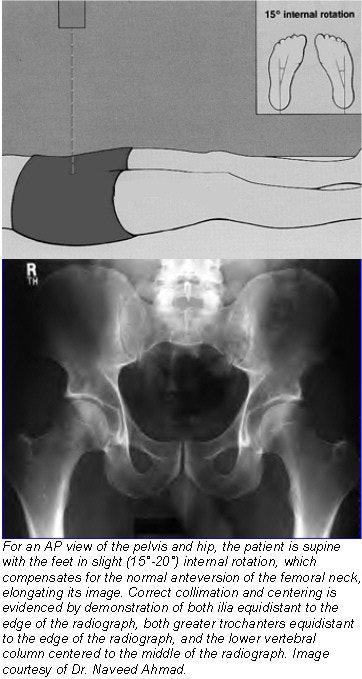
The standard radiographic view for the pelvis is obtained in an AP position with the patient supine. Most traumatic conditions involving the sacral wings, the iliac bones, ischium, the pubis, and the femoral head and neck can sufficiently be evaluated on the AP projection of the pelvis and hip. This view also demonstrates an important anatomical relationship in the longitudinal axes of the femoral neck and shaft. Normally, the angle formed by these axes ranges from 125°-135°. Varus and valgus configuration of a femoral neck fracture is said to occur if there is decrease or increase, respectively, in this angle.
Technical factors
- Image receptor (IR): 14 x 17 inch (35 x 43 cm) crosswise
- 75- 85 kVp range
- mAs 12 (at 80 kVp)
- Moving or stationary grid
- Surface-to-image distance (SID) of 40 inches (100 cm)
- The patient is positioned supine on the radiographic table, with arms placed at the side or across the upper chest. Placing a support under the head and knee helps to relieve the strain on the patient while in the supine position.
- The midsagittal plane of the body should be centered to the midline of the grid device. There should be no rotation of the pelvis. The distance from tabletop to each anterior superior iliac spine (ASIS) should be equal.
- The feet are placed in approximately 15°-20° of internal (medial) rotation. This is done to overcome the normal anteversion of the femoral necks and to place their longitudinal axes parallel to the film. The heels should be 8-10 inches (20-24 cm) apart.
- For correct centering of the pelvis (bilateral hips), palpate for the iliac crest and adjust the position of the cassette so that the upper border of the cassette is 1-1 ½ inches (2.5-3.8 cm) above the iliac crest. The center of the cassette should be midway between the ASIS and the pubic symphysis.
- For a pelvis with bilateral hips projection, carefully palpate the superior portion of the iliac crest and direct the central ray (CR) midway between the level of the ASIS and the symphysis pubis.
- Shield gonads on all male patients. Ovarian shielding on females, however, is generally not possible without obscuring essential pelvic anatomy (unless interest is in area of hips only).
- Ask the patient to suspend their breathing on expiration.
- The entire pelvis along with proximal femoral neck including pelvic girdle, L5, sacrum, and coccyx should be seen.
- The lesser trochanters usually are not visible at all, or if they are, should appear equal in size and shape on the medial border of the femora. The greater trichinae should be visible in profile.
- No rotation is evidenced by symmetric appearance of the two obturator foramina, as well as a symmetric iliac alae and ischial spines. A closed or narrowed obturator foramen indicates rotation in that direction.
- Correct collimation and centering is evidenced by demonstration of both ilia equidistant to the edge of the radiograph, both greater trochanters equidistant to the edge of the radiograph, and the lower vertebral column centered to the middle of the radiograph.
- Optimal exposure should clearly demonstrate L5, sacral area, and margins of the femoral heads and acetabula without overexposing the ischium and the pubic bones.
- No motion is evidenced by sharp orbicular markings of the proximal femora and the pelvic structures.
 |
AP unilateral hip projection
An AP unilateral hip study is usually a postoperative or a follow-up exam to demonstrate the acetabulum, femoral head and neck, and the greater trichinae, as well as the condition and placement of any existing orthopedic appliance. Technical factors and patient positioning are the same as for an AP pelvis (bilateral hips) exam.
The CR is placed perpendicular to the femoral neck in question, approximately 2 ½ inches (6.4 cm) distal on a line drawn perpendicular to the mid point of a line between the ASIS and the pubic symphysis. In other words, the CR is directed 1-2 inches (2.5-5 cm) distal to mid femoral neck.
The femoral neck can be located about 1-2 inches (3-5 cm) medial and 3-4 inches (8-10 cm) distal to the ASIS. The collimated field should demonstrate the femoral head and neck, trochanters, the proximal third of the femur shaft, regions of the ilium, and the pubic bones adjoining the pubic symphysis.
The greater trochanter and femoral head and neck should be in full profile without foreshortening. The lesser trochanter should not project beyond the medial border of the femur. Optimal exposure should ensure visualization of the femoral head through the acetabulum.
AP oblique pelvis projection x-ray positioning techniques
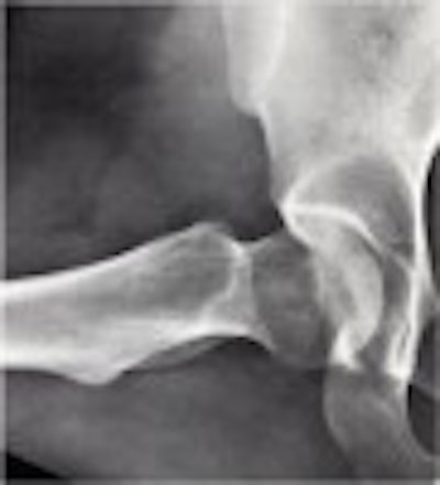
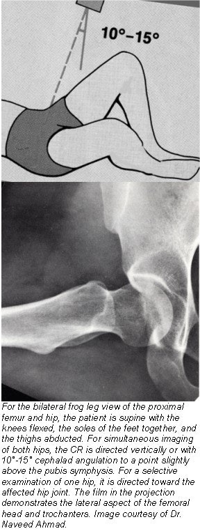
This projection is also called the bilateral “frog leg” position. It is useful for demonstration of a non-trauma hip or developmental dysphasia of the hip, also known as congenital hip dislocation (CHD). It shows an AP oblique projection of the femoral heads, necks, and the trochanteric areas projected onto one radiograph for comparative purposes.
Technical factors
- IR: 14 x 17 inch (35 x 43 cm) crosswise
- 75-85 kVp range
- mAs of 12 (at 80 kVp)
- Moving or stationary grid
- SID of 40 inches (100 cm)
- The patient is positioned supine on the radiographic table, arms placed at the side or across the upper chest. Placing a support under the head helps relieve the strain on the patient while in the supine position.
- The midsagittal plane of the body should be centered to the midline of the grid device. There should be no rotation of the pelvis. The distance from tabletop to each ASIS should be equal.
- For a bilateral projection, both hips and knees are flexed approximately 90°. Have the patient draw the feet up as much as possible. After correctly centering the cassette 1 inch (2.5 cm) superior to the pubic symphysis, abduct both thighs approximately 45° from the vertical plane to place the long axis of femoral necks parallel with the plane of the cassette. Ensure that both thighs are abducted the same amount and that pelvis is not rotated (equal distance of both ASIS to the tabletop). Have the patient turn their feet to brace the soles against one another for support.
- For unilateral frog leg projection center the ASIS of the affected side to the midline of the grid. Ask the patient to flex the hip and knee of the affected side, then abduct the thigh laterally, approximately 45°. Have the patient draw the foot up to the opposite knee as much as possible so that the sole of the foot is against the opposite knee. The pelvis may rotate slightly in a unilateral projection.
- Carefully palpate the superior portion of iliac crest and direct the CR to a point 3 inches (7.5 cm) below the level of the ASIS (1 inch or 2.5 cm above symphysis pubis). For the unilateral position, direct the CR to the femoral neck.
- Shield gonads on all male patients. Ovarian shielding on females, however, is generally not possible without obscuring essential pelvis anatomy (unless interest is in area of hips only).
 |
Evaluation criteria
- Femoral heads and necks, acetabulum, and trochanteric areas should be visible on a single radiograph.
- No rotation is evidenced by symmetric appearance of the two obturator foramina and pelvic bones. The lesser trochanters should appear equal in size as projected on the medial margins of the femora. The greater trochanters are superimposed over the femoral necks.
- The femoral heads and necks and trochanters should appear symmetric if both thighs are abducted equally.
Other special radiographic projections to evaluate injury to the pelvic girdle include the AP axial outlet projection, AP axial inlet projection, oblique projections for acetabulum, groin projections (axiolateral), and posterior oblique projections for SI joints. These are usually requested in trauma patients after a routine AP projection shows some pathology, or in postsurgical patients who need follow-up evaluation.
AP axial pelvic outlet and AP axial pelvic inlet projections
The AP axial outlet projection shows an elongated projection of the pubic and ischial rami. This projection provides an excellent view of the bilateral pubes and ischia to assess pelvic bones for fractures and displacements. The AP axial inlet projection provides assessment of the pelvic ring.
The technical factors and patient positioning for these projections are the same as for an AP pelvis projection. The main difference lies in the CR angulations.
For an AP axial outlet projection, the CR is angulated cephalad 20°-35° for males and 30°-45° for females and is centered to a point 2 inches (5 cm) distal to the superior border of the pubic symphysis. For an AP axial inlet projection, the CR is angulated caudad 40° and is centered to a midline point at the level of both ASIS.
Oblique projections of the acetabulum
Oblique projections, known as Judet’s views, are necessary to evaluate the acetabulum. The anterior (internal) oblique projection helps delineate the anterior column and the posterior rim of the acetabulum. The posterior (external) oblique projection delineates the posterior column and the anterior acetabular rim.
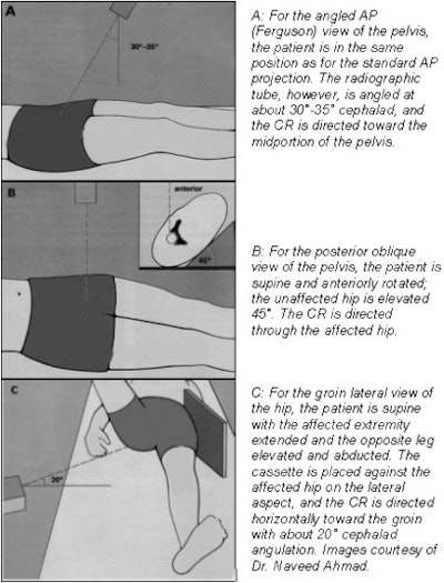
For a posteroanterior (PA) oblique projection the patient lies in a semi-prone position on the affected side. The unaffected side is elevated so that the anterior surface of the body forms a 38° angle from the table. The CR is directed 12° cephalic to the side being examined, approximately 2 inches (5 cm) lateral to the midsagittal plane at the inferior level of coccyx, permitting the CR to be directed through the acetabulum.
 |
Axiolateral projection of the hip and proximal femur (groin projection)
The groin projection is particularly useful in evaluating anterior and posterior displacement of fracture fragments in proximal femoral fractures, as well as the degree of rotation of the femoral head. This projection provides a true lateral image of the proximal femur and also demonstrates an important anatomic feature, the angle of the anteversion of the femoral neck, which normally ranges from 25°-30°.
It may be done on a stretcher or at bedside if the patient cannot be moved. The unaffected leg is elevated and flexed so that the unaffected thigh is outside the collimation field. The IR is placed in a crease above the iliac crest so that it is parallel to the femoral neck and perpendicular to the CR. If the limb can be safely moved, internally rotate the foot about 15° by grasping the heel to overcome the anteversion of the femoral neck. The CR is directed to the femoral neck and to IR.
Oblique projection for the SI joints
Various methods have been used to examine the sacroiliac joints; however, none is ideal as the normal undulating articular surfaces make evaluation of these joints extremely difficult. An angled AP radiograph can be taken with the tube angulated 30°-35° in a cephalad direction.
This projection is known as a Ferguson view. It not only shows the SI joints to a better advantage but also helps in more effectively evaluating injury to the sacral bone, the pubis, and the ischial rami. Some radiologists prefer a PA radiograph with 25°-30° of caudal angulation of the tube to evaluate the SI joints. In either case, both sacroiliac joints are exposed on a single film, facilitating a comparative evaluation.
By Dr. Naveed Ahmad
AuntMinnie.com contributing writer
August 8, 2003
Related Reading
The lowdown on lumbar spine positioning, June 19, 2003
Radiographic positioning techniques for the cervical spine, March 26, 2003
Boning up on humerus, clavicle, and AC joint positioning, February 18, 2003
Getting the most from shoulder positioning, December 24, 2002
The bends and flexures of forearm and elbow x-ray positioning, November 21, 2002
Copyright © 2003 AuntMinnie.com


